Apache NuttX and small systems - CAN node example

The previous posts in this series provided useful information about small systems and NuttX, but the code examples lacked practical value. Now, we move on to more practical, real-life applications that actually do something useful.
We begin with a simple CAN Bus node, which can be used to test CAN network setups or drivers, making it a handy tool for developers. Additionally, it can serve as a ready-to-use foundation for more complex applications.
Our goal here is to check and compare the resource usage of two CAN implementations available in NuttX: one based on the CAN character device and the other using the SocketCAN network interface. This comparison may be useful for developers deciding which solution to choose when working with CAN Bus on NuttX.
The entire test setup is built using accessible development kits, and thanks to NuttX's architecture, the implementation can be easily portable across different hardware.
Simple CAN Node
A ready-to-compile code is availalbe in the railab NuttX examples repository.
The application is designed to be POSIX-compliant and hardware-independent, and provides the following features:
Sends a periodic heartbeat every second, including the device system time in the message data.
Reads the button state and transmits it over CAN, notifying only when the button state changes.
Sets the LED state according to requests received for the node on CAN.
This implementation omits CAN error handling and additional diagnostic features for the device. Support for CAN extended IDs and CAN FD is also not included.
The application uses a simple protocol, where the CAN ID identifies both the device node and the message type:
The Message ID specifies the type of message on the bus and can be one
of the following:
ID |
Direction |
Message |
Data |
|---|---|---|---|
1 |
Out |
Heartbeat |
8B POSIX timestamp |
2 |
Out |
Button state |
1B button state |
3 |
In |
LED state |
1B LED state |
The Node ID is used to identify the device on the bus and can be configurable
via the Kconfig CONFIG_RAILAB_MINIMAL_CANNODE_NODEID option. Standard CAN ID
is 11 bits and only the 3 most significant bits are used as Node ID, so this
value must fit into the 0x700 mask.
As per the purpose of this post, the application can be compiled in two variants: one that uses the character device approach, and the other that uses the network interface. Depending on the configuration options, a given variant is used:
config RAILAB_MINIMAL_CANNODE_CHARDEV
  bool "CAN character device"
  depends on CAN

config RAILAB_MINIMAL_CANNODE_SOCKET
  bool "CAN SocketCAN interface"
  depends on CAN && NET_CAN

config RAILAB_MINIMAL_CANNODE_INVAL
  bool "CAN interface not selected"

endchoice # CAN stack used
The application uses a simple generalized CAN interface:
/* Common CAN message format for chardev and SocketCAN */

struct canmsg_s
  {
    uint32_t id;                    /* CAN message ID */
    uint8_t  len;                   /* CAN message data length */
    uint8_t  data[CAN_DATA_MAX];    /* CAN message data */
  };

/* Initialize CAN interface */

int can_init(void);

/* Get data from CAN interface (blocking) */

int can_read(int fd, FAR struct canmsg_s *msg);

/* Write data to CAN interface */

int can_send(int fd, FAR struct canmsg_s *msg);
The implementation of this interface can be found in:
-
cannode_char.c for CAN character driver, and
-
cannode_sock.c for SocketCAN interface.
All application features are identical in both variants, so we can easily compare the costs of both solutions.
Each node feature is provided in separate thread:
main()after initializing other components becomes responsible for periodic heartbeat transmition.thread_rx()read messages from CAN Bus and handle LED requests.thread_button()waits for button state change and send reports about button state on CAN Bus.
All read operations are blocking, so a thread is only woken up when there is something to process.
For implementation details, please visit application sources on Github.
Console support
Console support in the final application is often a waste of resources for small systems, but it's extremely helpful during development. For this, it's always good to keep logging features controlable with Kconfig option. This can be done with a simple macros:
/* Debug prints */

#ifdef CONFIG_SERIAL
#  define PRINTF(format, ...) printf(format, ##__VA_ARGS__)
#else
#  define PRINTF(...)
#endif
During development, if possible, we can use an MCU with more resources available, so we are not limited in debug capabilities. After everything works as expected, we disable all excessive features so the application fits into our target chip.
We can maintain multiple configurations with various debug levels enabled. When we use NuttX with the CMake build system, working simultaneously with many out-of-tree builds is straightforward. This is a big advantage of CMake which is relatively new in NuttX, but drastically changes the developer experience and productivity.
Configuration
We use the same board as in previous posts in this series - NUCLEO-F302R8 based on the STM32F302R8.
Complete configurations can be found at:
mini_cannode_char/defconfig for version with CAN character device.
-
mini_cannode_sock/defconfig for version with SocketCAN interface.
The most important parts of the configuration are presented below:
-
LED control from user-space is enabled with:
-
Button support with interrupt notifications is enabled with:
CONFIG_ARCH_BUTTONS=y
CONFIG_ARCH_IRQBUTTONS=y
CONFIG_INPUT=y
CONFIG_INPUT_BUTTONS=y
CONFIG_INPUT_BUTTONS_DEBOUNCE_DELAY=10
CONFIG_INPUT_BUTTONS_LOWER=y
Additionally
CONFIG_STM32_SYSCFGmust be set to support GPIO interrupts.Without this option, GPIO interrupts just won't work without any obvious errors reported, which can be difficult to debug for users. By default, this option is enabled in NuttX, but during optimization in earlier parts of this series, we disabled it to save some FLASH memory.
-
CAN support for STM32 requires:
CAN Bit timings are optimized to work on a given MCU with 250 kbit/s bitrate, thanks to bittiming.can-wiki.info for help.
At default STM32 port supports CAN character device, SocketCAN interface is enabled with an
CONFIG_STM32_CAN_SOCKET=yoption.CAN character device configuration is simple:
It's possible that there are two pending messages on the CAN TX FIFO, so we have to increase the default FIFO size from 8 to 16.
In the case of SocketCAN, configuration is more complex, because we have to configure network stack. The minimum working configuration is:
# CONFIG_NET_ETHERNET is not set
# CONFIG_NET_IPv4 is not set
CONFIG_IOB_BUFSIZE=64
CONFIG_IOB_NBUFFERS=5
CONFIG_NET=y
CONFIG_NETDEV_LATEINIT=y
CONFIG_NET_CAN=y
CONFIG_NET_PREALLOC_DEVIF_CALLBACKS=2
CONFIG_SCHED_LPWORK=y
The IOB buffer could be configured more efficiently to save a few bytes of SRAM. However, finding the optimal value is insignificant here, as we're more interested in FLASH consumption than SRAM.
CAN Bus Demo
The test setup used to verify if the code works correctly is shown below:
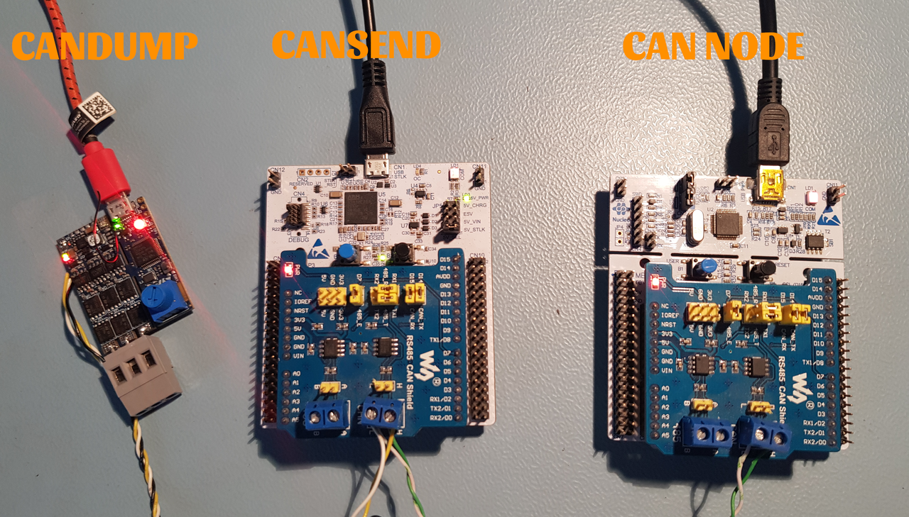
Our simple CAN node is connected to two devices with SocketCAN utilities onboard.
One device is used to send LED requests using the cansend tool, while the
other is used to capture CAN traffic with the candump tool. The boards used
in this demo are the NUCLEO-F302R8 for the CAN node and the NUCLEO-G431RB next
to the B-G431B-ESC1 for SocketCAN utilities.
The Nucleo boards are equipped with the Waveshare CAN Shield, which is based on the SN65HVD230 CAN transceiver, while the B-G431B-ESC1 has an onboard TCAN330DCNT CAN transceiver.
LED requests are sent with these commands:
cansend can0 103#01which turn LED on,cansend can0 103#00which turn LED off.
An example of CAN network traffic with an explanation is shown below:
nsh> candump can0
  can0  101   [8]  00 00 00 00 00 00 00 00   | node reset
  can0  102   [1]  00                        | button state
  can0  101   [8]  50 69 0F 00 00 00 00 00
  can0  101   [8]  A0 D2 1E 00 00 00 00 00
  can0  101   [8]  F0 3B 2E 00 00 00 00 00
  can0  101   [8]  40 A5 3D 00 00 00 00 00
  can0  102   [1]  01                        | button press
  can0  102   [1]  00                        | button release
  can0  101   [8]  90 0E 4D 00 00 00 00 00
  can0  101   [8]  E0 77 5C 00 00 00 00 00
  can0  101   [8]  30 E1 6B 00 00 00 00 00
  can0  101   [8]  80 4A 7B 00 00 00 00 00
  can0  102   [1]  01                        | button press
  can0  101   [8]  D0 B3 8A 00 00 00 00 00
  can0  101   [8]  20 1D 9A 00 00 00 00 00
  can0  101   [8]  70 86 A9 00 00 00 00 00
  can0  101   [8]  C0 EF B8 00 00 00 00 00
  can0  102   [1]  00                        | button release
  can0  101   [8]  10 59 C8 00 00 00 00 00
  can0  101   [8]  60 C2 D7 00 00 00 00 00
  can0  101   [8]  B0 2B E7 00 00 00 00 00
  can0  103   [1]  01                        | set LED
  can0  101   [8]  00 95 F6 00 00 00 00 00
  can0  101   [8]  50 FE 05 01 00 00 00 00
  can0  101   [8]  A0 67 15 01 00 00 00 00
  can0  103   [1]  00                        | reset LED
  can0  101   [8]  F0 D0 24 01 00 00 00 00
  can0  101   [8]  40 3A 34 01 00 00 00 00
  can0  101   [8]  90 A3 43 01 00 00 00 00
  can0  103   [1]  01                        | set LED
  can0  101   [8]  E0 0C 53 01 00 00 00 00
  can0  101   [8]  30 76 62 01 00 00 00 00
  can0  101   [8]  80 DF 71 01 00 00 00 00
  can0  101   [8]  D0 48 81 01 00 00 00 00
  can0  101   [8]  20 B2 90 01 00 00 00 00
Results
Memory report for the complete application with the CAN character device version:
and for the heartbeat-only feature:
Memory report for the complete application with the SocketCAN version:
and for the heartbeat-only feature:
The functionality of both applications is identical, but SocketCAN consumes an additional 3776 bytes of FLASH and 940 bytes of SRAM for a complete applicaton.
Additionally, the application consumes 512 bytes of SRAM for each thread in the system:
IDLE thread,
main(),thread_rx()when LED support is enabled,thread_button()when button support is enabled,and for SocketCAN only: the worker thread enabled with
CONFIG_SCHED_LPWORK.
Summary
In both cases, the application remains under 32KB of FLASH, leaving some room to add more useful features. Scaling the application to support additional buttons or LEDs should require minimal resources, as most of the necessary logic is already embedded in the firmware.
The CAN interface based on the character driver is slightly more resource-efficient compared to the SocketCAN version. Implementing user code with the character driver is also simpler, as it eliminates the need to work with sockets.
For projects with strict resource constraints, it's advisable to avoid SocketCAN unless absolutely necessary. Unless you are porting existing SocketCAN—based code or require another network interface in your application—making the cost of network abstraction irrelevant—the character driver is the preferred choice for small systems.
Comments