Apache NuttX and small systems - Modbus slave example
It’s time for another hands-on example of using NuttX in small embedded systems! This time, we’ll dive into implementing a simple application with Modbus RTU, a lightweight and cost-effective industrial protocol. Thanks to its low implementation cost, Modbus RTU is a great choice for cheap, resource-constrained microcontrollers.
In this example, we’ll demonstrate how to use Modbus for remote reading of analog inputs, a common task in industrial applications that can be use to read sensor signals or measure electrical parameters. We’ll take a closer look at the memory footprint of the Modbus slave stack in NuttX and the resources requirements to support ADC on STM32 devices.
Simple Modbus Slave
The complete source code of the example can be foun in apps/mini_modbusslave. The application is designed to be POSIX-compliant and hardware-independent.
Application features include:
-
Communication with Modbus RTU over RS-485 using standard Modbus parameters:
8 data bits,
1 parity bit with event parity,
19200 bps.
Return the state of 4 analog inputs in millivolts. Channels are sampled one by one when a single trigger occurs.
-
Gather some statistics about analog data:
minimal channel value,
maximum channel value,
exponential moving average (EMA) for channel.
Statistics can be reset by writing to a Modbus register, and the sampling time is configurable via Modbus protocol.
-
Return device state:
a flag indicating whether the ADC thread is running,
a simple counter that increments every second.
The Modbus Slave ID is hardcoded but configurable through Kconfig with
the CONFIG_RAILAB_MINIMAL_MODBUSSLAVE_SLAVEID option.
RS-485 parameters are fixed and set at the configuration level.
Each node feature is provided in a separate thread:
main()- after initializing other components, it's responsible for increasing the device state counter.thread_adc()- handles ADC sampling and store samples with statistics in memory.thread_modbus()- manages Modbus communication.
ADC sampling is triggered by software, simple usleep() is used to control
the sampling interval. All channels are sampled after a single software trigger.
To avoid losing samples, the ADC is configured to work with DMA. This eliminates
the need for an additional timer to trigger the ADC, and the time accuracy
remains sufficient for this kind of application. This approach is the most
resource-efficient.
The FreeModBus stack available in NuttX requires the use of global data. Shared data are protected with mutex:
/* Modbus input registers */

begin_packed_struct struct modbus_input_s
{
  uint16_t status;
  uint16_t cntr;
  int16_t  now[ADC_SAMPLES];    /* Sample now in mV */
  int16_t  min[ADC_SAMPLES];    /* Sample min in mV */
  int16_t  max[ADC_SAMPLES];    /* Sample max in mV */
  int16_t  avg[ADC_SAMPLES];    /* Sample exponential moving average in mV */
} end_packed_struct;

/* Modbus holding registers */

begin_packed_struct struct modbus_holding_s
{
  uint16_t interval;  /* Sampling interval */
  uint16_t rst_stats; /* Reset statistics */
} end_packed_struct;

/* Modbus state */

struct modbus_state_s
{
  struct modbus_input_s   input;    /* Input state */
  struct modbus_holding_s holding;  /* Holding state */
  pthread_mutex_t         lock;     /* Data lock */
};
An alternative to using a mutex is to use an rwlock, but based on previous experiments, we opted for the slightly lighter solution.
A list of registers supported by our application is presented below:
Address |
R/W |
Description |
Type |
|---|---|---|---|
1 |
R |
Device status |
uint16_t |
2 |
R |
Seconds counter |
uint16_t |
3-6 |
R |
ADC channel 0-4 value |
int16_t (mV) |
7-10 |
R |
ADC channel 0-4 minimum value |
int16_t (mV) |
11-15 |
R |
ADC channel 0-4 maximum value |
int16_t (mV) |
16-19 |
R |
ADC channel 0-4 EMA value |
int16_t (mV) |
32 |
RW |
ADC statistics reset |
uint16_t |
33 |
RW |
ADC sampling interval |
uint16_t |
Configuration
Complete configurations can be found at mini_modbusslave/defconfig.
The most important parts of the configuration are presented below:
-
ADC support with DMA transfer is enabled with:
-
The number of allocated interrupts must be large enough to fit all DMA handlers:
CONFIG_ARCH_MINIMAL_VECTORTABLE=y
CONFIG_ARCH_MINIMAL_VECTORTABLE_DYNAMIC=y
CONFIG_ARCH_NUSER_INTERRUPTS=13
Currently, the STM32 port in NuttX registers interrupt for all possible DMA channels, even if a DMA channel is not in use.
-
UART parameters used for Modbus are configured directly from the configuration to avoid using the
termiosinterface: -
The size of UART buffers has been selected to accommodate the maximum supported frame for Modbus RTU, which is 256 bytes:
-
We use the FreeModBus port availalbe in NuttX, and all unused protocol features are disabled:
# CONFIG_MB_ASCII_ENABLED is not set
# CONFIG_MB_FUNC_OTHER_REP_SLAVEID_ENABLED is not set
# CONFIG_MB_FUNC_READWRITE_HOLDING_ENABLED is not set
# CONFIG_MB_FUNC_READ_COILS_ENABLED is not set
# CONFIG_MB_FUNC_READ_DISCRETE_INPUTS_ENABLED is not set
# CONFIG_MB_FUNC_WRITE_COIL_ENABLED is not set
# CONFIG_MB_FUNC_WRITE_MULTIPLE_COILS_ENABLED is not set
# CONFIG_MB_TCP_ENABLED is not set
CONFIG_MODBUS=y
CONFIG_MODBUS_SLAVE=y
The rest of the configuration and its optimization for small systems was presented in the previous parts of this series, so there is no point in repeating it here.
Modbus Slave Demo
The test setup used to verify if the code works correctly is shown below:
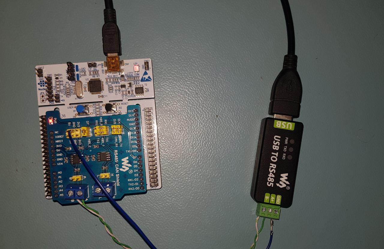
The same board used in the previous posts of this series—NUCLEO-F302R8, based on the STM32F302R8—is used here. The Nucleo board is equipped with the Waveshare RS485/CAN Shield, which features a MAX3485 transceiver.
For the following tests, we used the mbpoll tool as a Modbus master to poll our device.
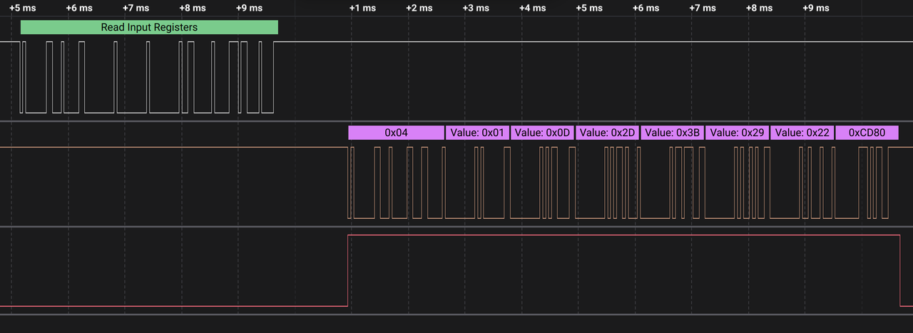
First, let's read the ADC samples from the device:
# read device state and current ADC samples

[raiden00:~]$ mbpoll -q -1 -a 1 -t 3 -r 1 -c 6  /dev/ttyUSB0
-- Polling slave 1...
[1]:  1           # device state
[2]:  721         # dummy counter
[3]:  422         # ADC ch0 in mV
[4]:  531         # ADC ch1 in mV
[5]:  626         # ADC ch2 in mV
[6]:  467         # ADC ch3 in mV

# read device state, current ADC samples and statistics

[raiden00:~]$ mbpoll -q -1 -a 1 -t 3 -r 1 -c 18  /dev/ttyUSB0
-- Polling slave 1...
[1]:  1           # device state
[2]:  756         # dummy counter
[3]:  303         # ADC ch0 in mV
[4]:  274         # ADC ch1 in mV
[5]:  268         # ADC ch2 in mV
[6]:  290         # ADC ch3 in mV
[7]:  115         # ADC ch0 min val in mV
[8]:  207         # ADC ch1 min val in mV
[9]:  174         # ADC ch2 min val in mV
[10]: 152         # ADC ch3 min val in mV
[11]: 2640        # ADC ch0 max val in mV
[12]: 2364        # ADC ch1 max val in mV
[13]: 3294        # ADC ch2 max val in mV
[14]: 3300        # ADC ch3 max val in mV
[15]: 293         # ADC ch0 EMA val in mV
[16]: 268         # ADC ch1 EMA val in mV
[17]: 269         # ADC ch2 EMA val in mV
[18]: 298         # ADC ch3 EMA val in mV
Next, let's modify the sampling interval:
# read interval

[raiden00:~]$ mbpoll -q -1 -t4 /dev/ttyUSB0 -r 31
-- Polling slave 1...
[31]:         10000

# write new interval

[raiden00:~]$ mbpoll -t4 /dev/ttyUSB0 -r 31 12345
Written 1 references.

# read interval

[raiden00:~]$ mbpoll -q -1 -t4 /dev/ttyUSB0 -r 31
-- Polling slave 1...
[31]:         12345
And finally, let's check if resetting the analog statistics works:
# read ADC stats only

[raiden00:~]$ mbpoll -q -1 -q -a 1 -t 3 -r 7 -c 12  /dev/ttyUSB0
-- Polling slave 1...
[7]:  15          # ADC ch0 min val in mV
[8]:  47          # ADC ch1 min val in mV
[9]:  60          # ADC ch2 min val in mV
[10]: 0           # ADC ch3 min val in mV
[11]: 2786        # ADC ch0 max val in mV
[12]: 2823        # ADC ch1 max val in mV
[13]: 2570        # ADC ch2 max val in mV
[14]: 3118        # ADC ch3 max val in mV
[15]: 396         # ADC ch0 EMA val in mV
[16]: 453         # ADC ch1 EMA val in mV
[17]: 510         # ADC ch2 EMA val in mV
[18]: 390         # ADC ch3 EMA val in mV

# reset stats

[raiden00:~]$ mbpoll -q -t4 /dev/ttyUSB0 -r 32 1
Written 1 references.

# read ADC stats once again

[raiden00:~]$ mbpoll -q -1 -q -a 1 -t 3 -r 7 -c 12  /dev/ttyUSB0
-- Polling slave 1...
[7]:  189         # ADC ch0 min val in mV
[8]:  209         # ADC ch1 min val in mV
[9]:  242         # ADC ch2 min val in mV
[10]: 220         # ADC ch3 min val in mV
[11]: 548         # ADC ch0 max val in mV
[12]: 630         # ADC ch1 max val in mV
[13]: 716         # ADC ch2 max val in mV
[14]: 607         # ADC ch3 max val in mV
[15]: 391         # ADC ch0 EMA val in mV
[16]: 451         # ADC ch1 EMA val in mV
[17]: 513         # ADC ch2 EMA val in mV
[18]: 406         # ADC ch3 EMA val in mV
The device performs as expected, so we can move on to the resource usage summary.
Results
Memory report for the complete application is:
Memory report with ADC sampling disabled and Modbus stack enabled:
Memory report with the Modbus stack disabled and ADC sampling enabled:
Additionally, the application consumes 512 bytes of SRAM for each thread in the system:
IDLE thread,
main(),thread_modbus()(when Modbus support is enabled),thread_adc()(when ADC support is enabled).
For this specific example, we can estimate that Modbus support takes 4464 bytes of FLASH and ADC support takes 4024 bytes of FLASH.
Looking at the symbols in the binary, I see some potential for further optimization:
We don’t need
syslog(), but the logic related to it hasn't been removed. If we know that our application doesn’t require this feature, we should be able to completely disable SYSLOG during system configuration.In our case, the serial port configuration is done at the NuttX configuration level. We don’t need the
termiosfunctions to be called from the Modbus stack, but currently, there is no option to disable this logic.The compiler doesn't optimize
adc_ioctl()well, leaving some unused logic in the image.As mentioned earlier, DMA handlers should only be used when a specific DMA channel is in use. It makes no sense to allocate interrupts for all DMA channels present in the chip.
Summary
Just like in our previous practical example with CAN node, one again we managed to fit the application within 32KB of FLASH. Analyzing the final binary, I see potential for further optimization, making it possible to bring the size below 30KB, though this would require modifications to the NuttX source—a topic for another time.
Some key features of a fully functional Modbus device have been intentionally omitted to simplify implementation. However, the provided code serves as a solid foundation for further development, such as:
configuring Modbus parameters like baud or slave ID form the program,
applying scale and offset for returned ADC samples,
adding a system watchdog,
or including more signal statistics.
There is plenty of room for further improvements, but even in its current form, the application can be useful for prototyping Modbus-based applications.
Comments